

Can we estimate the distance to a vehicle with cameras only?
It is possible to experience distance estimation on a camera image by leveraging a stereo camera system. In stereo vision, we use two stereo images from two cameras to perform disparity estimation and, next, compute depth. From there, it is possible to estimate the distance to a vehicle. Accurate depth estimation from cameras is a significant computer vision problem, yet to be solved entirely with a lot of ongoing research.
This article will explore stereo depth estimation using a stereo-matching technique to try to answer this question. You can see the final result of this project on the KITTI dataset below, in which we use left and right images.
But what is the disparity?
Disparity Vs Depth Estimation
In a nutshell, to get the depth, first, we need to compute the disparity. The same scene can be captured by two cameras mounted in a stereo system, but the corresponding pixel points of the image pair will have different coordinates. The disparity is the distance between these two sets of coordinates for the same scene point. In other words, the disparity measures the displacement of the image points between two frames. If we compute the disparity for each corresponding pixel on the image, the output will be the disparity map.
Computing the disparity map is essential because it allows us to retrieve the depth information and output the depth map of the image, which can be helpful to know how far a vehicle is or for other applications such as 3D reconstruction. If you are interested in 3D, I also wrote about 3D perception here and 3D deep learning here.
Once the disparity has been estimated, it is possible to estimate the depth. Once we have the depth, it becomes straightforward to calculate the distance. With an object detector, such as YOLO, we can detect the objects of interest and estimate their distance. But how does it work? Below is the diagram of the stereo camera model.

The depth Z is the distance between a point P in the real world and the camera. This diagram presents a stereo vision system with two parallel cameras, C and C’. The distance B between the cameras is called the baseline, f is the focal length, and x and x’ are the image planes of the cameras C and C’.
By triangulation, we can compute the depth Z with the following formula, where (x - x’) is the disparity:
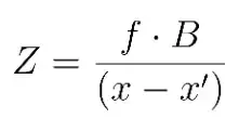
From the above equation, it is essential to note that depth and disparity are inversely proportional. In other words, the greater the depth, the lesser the disparity, and the lesser the depth, the greater the disparity.
Now, we know how to get the depth granted that we know the disparity. It is a crucial step as it opens the doors to 3D reconstruction and 3D computer vision. But wait! How do we compute the disparity?
Epipolar Geometry and Disparity Estimation
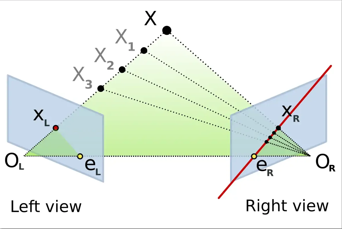
First, let’s look at a diagram of a stereo camera model where two cameras look at the same point, X.
What is an Epipolar Line
The line Ol - X represents the point X seen on the left image, directly aligned to its camera center, or optical center OL. On the right image, this line materialized by the line (eR - XR) is called the epipolar line. Similarly, the line OR - X represents a point for the right camera, but for the left camera, this is materialized by the epipolar line eL-XL. Because the two cameras must be similar in stereo vision, the horizontal line on the left image is the same horizontal line on the right image. The goal is to find the corresponding point on the right image plane so that we can draw the line that will intersect with X and get the disparity estimation.
What is an Epipolar Plane
To generalize the previous explanation, the plane X, OL, OR shown as a green triangle on the previous diagram is called the epipolar plane.
Observation on the Epipolar Constraint
If the relative position of the two cameras is known, it is possible to test whether two points correspond to the same 3D points because of the epipolar constraint. The epipolar constraint means that the projection of X on the right camera plane xR must be contained in the eR–xR epipolar line.
Finally, it is essential to note that epipolar constraints can be described algebraically by the fundamental matrix.
Disparity Estimation With Semi Global Block matching
There are different stereo matching algorithms to estimate the disparity. One traditional stereo matching method is semi-global block matching. It’s fast to implement, but it can lack accuracy, and it is computationally intensive.
However, it can be a good starting point, and depending on your use case; it might already solve your problem. This algorithm is faster than global block matching and more accurate than local block matching. It is also suitable to be run on ASIC and FPGA. Because of these improvements, it can be a reliable and real-time algorithm used in robotics and autonomous driving.
The method of semi-global block matching is an intensity-based algorithm used to compute the dense disparity from a pair of two input images. It works by analyzing the similarity between pixels in multiple directions.
To run this algorithm, it is crucial to use rectified stereo images. Hence, the epipolar lines are parallel with the horizontal axis and match the vertical coordinates of each corresponding pixels.
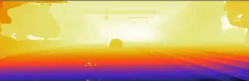
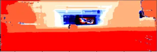
The image below shows the disparity map computed on the KITTI dataset using the semi-global block matching algorithm.
If the results with the semi-global block matching algorithm are not good enough for your use case, the next step is to implement deep learning methods, but it takes more time to develop as it is more complex. Applying neural networks for depth estimation is a very active research area in computer vision.
Depth Map Estimation From Disparity
As explained above, we first need to compute the disparity to estimate the depth, as we just did. We can output the depth map from there by implementing the equation above. Below is the depth map I got after computing the disparity map.
With a stereo camera system and their corresponding image pairs, we now have the depth value of the corresponding pixels. In other words, we removed the 2D barrier due to the data structure of images, and we can work in 3D. In autonomous driving, it means that with two cameras recording pairs of left and right images, we can estimate the distance between our vehicle and an obstacle, which is essential for localization, motion planning, and control of the driverless car.
Other Depth Estimation Methods
As I mentioned earlier, there is a lot of ongoing research in depth estimation, in particular, on the use of neural networks to perform depth estimation in stereo vision systems, but also to develop monocular depth estimation methods in which we would use monocular images from one camera to estimate depth. If you are interested, I have implemented a monocular depth estimation algorithm with a neural network here. Unfortunately, at the moment, these methods tend to be less accurate than stereo vision techniques.
Another method is to perform depth estimation using optical flow, a motion-based approach that can retrieve depth information.
Closing Thought on Stereo Vision
In this article, we briefly learned that it is possible to estimate the distance with at least two cameras, despite having images in 2D, by estimating the disparity and the depth of the image.
If you are curious, you can watch the final result here, where I go one step further by adding an object detector and getting the distance to a vehicle.
I used resources from Thinkautonomous.ai’s stereo vision course and Cyrill Stachniss’ lectures to prepare this article.
